
Newsletter Volume 11, Issue 3 September 2026
Estimating soil failure parameters from the Press-in data
Emeritus Professor
Civil Engineering Department
University of Tunis El Manar
National Engineering School of Tunis
Assistant Professor
Civil Engineering Department, Higher Institute of Environmental,
Urban Planning, and Building Technologies
University of Carthage
Abstract
Piling technologies patented by GIKEN LTD. (Japan) include the installation of retaining structures and foundations by different Press-in methods. The latter comprises several installation methods of steel piles, including tubular piles, sheet piles, etc. From the Press-in installation procedure, recorded force-displacement and torque-rotation curves versus depth are obtained. Analysis of those curves shows the variation of resistance of crossed soil (or rock) layers against the penetration either by downward vertical displacement or rotation with respect to the axis of steel piles. This contribution focuses on the estimation of shear strength parameters from recorded Press-In results by adopting a recently proposed method of determination using the cylindrical shear tool test. Analysis of an experienced IPA case study indicates that from ultimate recorded torque values, the determination of friction of gravel and undrained cohesion clay leads to realistic values. Whilst from the ultimate recorded force, one obtains good predictions of undrained cohesion and friction angle of silt sand soil.
1. Introduction
Geotechnical investigation can be performed in-situ and in the laboratory to characterize soils after test results including physical, chemical, mechanical and strength parameters. Laboratory tests cover short-term and long-term soil behavior; however, they are usually performed on specimens affected by disturbance. In-situ tests in destructive mode cover a wide range of soils, essentially dealing with the short-term behavior. Most current in-situ tests are conducted up to failure in view of estimating strength parameters. Static and dynamic cone penetration tests as well as standard penetration tests are extensively used in practice to estimate soil shear strength parameters via well-established correlations.
Recently, the Cylindrical Shear Tool (CST) was proposed and tested to determine the cohesion and friction angle of soils directly without making recourse to correlation. Based on the similarity between the practiced equipment of Press-in technologies, there is a way to estimate the shear strength parameters from recorded ultimate force and torque values during the installation of tubular piles and zero sheet piles to build retaining structures for various geotechnical applications.
The present paper summarizes, in brief, the method of determination of cohesion and friction angle from the CST. Then, relationships are derived between the recorded ultimate force and torque-rotation values and the resisting force and torque recorded when installing the Press-in equipment. Based on the similarity between the CST and a tubular pile, the predicted cohesion and friction angle for different soil types are interpreted.
2. Cylindrical shear tool
The cylindrical shear tool (CST) patented by Bouassida et al (2020 & 2022) is a cylindrical tube (Fig. 1), with a sharpened tip that enables performing a shear test by vertically penetrating the tool in a soil sample, either remolded or after intact extraction, at a prescribed rate of downward displacement. Using the CST, one performs only the shear phase that corresponds to the tool penetration into the soil. The CST has a regular contact area with the surrounding soil along which the resistance against the soil penetration is simply quantified. During the shear test, using the CST, the soil reaction developed over the lateral inner and outer areas of the tool is recorded. Along the soil-CST interface, the ultimate shear stress is described by the Mohr-Coulomb law given by Eq (1):
τ = C + σ tg δf (1)
C denotes the soil’s cohesion, and the angle δf denotes the friction angle of the interface between the CST and the soil.
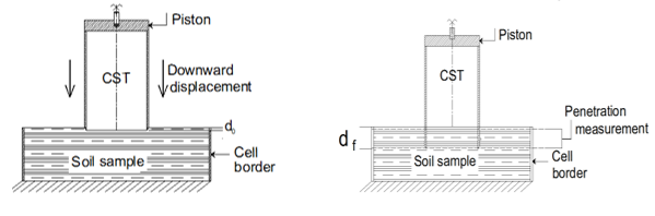
Fig. 1. Illustration of shear test conducted by the cylindrical shear tool (Azaiez & Bouassida, 2022).
δf = α φ 0.5 ≤ a ≤ 1 (2)
In Eq (1), the normal stress σ, corresponds to the horizontal stress acting on the lateral areas of the CST when penetrating the soil between the respective initial and final penetration values d0 and df (Fig. 1).
The ultimate force resulting from the developed shear stress given by Eq (3), proposed by Bouassida and Azaiez (2023), is written:
Pult = (0.5 γ dult2 tg δf Kp + C dult) π (Dout + Dinn) (3)
Kp is the coefficient of passive pressure determined from the soil friction angle via Eq (4):
The values of the ultimate force and the corresponding ultimate penetration are determined with an appropriate method from the recorded load-displacement curves during the CST test (Bouassida and Azaiez, 2023).
In case of a purely cohesive soil (φ = 0, C = Su: undrained cohesion), the ultimate force reduces to the value given by Eq (5):
From Eq (3), the ultimate force, Pult, associated with the ultimate penetration of the CST, dult, in a purely frictional soil (e.g. C = 0) is:
Dext and Dinn represent the external diameter and the inner diameter of the cylindrical shear tool, respectively.
Compared to the CPT, the procedure of the CST test is identical, but the contact between the conical tip and the soil is missing to identify the soil resistance in terms of the developed stress governed by Coulomb’s Eq (1). Therefore, there is a need to use correlations to determine the cohesion or the friction angle of the tested soil indirectly.
In the present paper, the objective is to estimate the cohesion and/or the friction angle of soil layers subject to the installation of a tubular pile using the Press-in technologies detailed in the handbook (IPA, 2021). The Press-in installation of a tubular pile results in recorded force and torque versus depth curves.
3. Estimation of failure characteristics from recorded Press-in Data
This estimation considers the following assumptions:
- Failure parameters (cohesion & friction angle) of each crossed layer of thickness H are constant.
- Only the shaft resistance is considered: it comprises two components of the resisting Press-in force and torque developed along the inner and outer lateral areas of the pile.
- The tip resistance vanishes since the area of the tubular pile base is negligible compared to lateral areas.
Fig. 2 shows an example of recorded force and torque versus depth during the installation of a steel tubular pile of 16 m length and outer diameter of 1.0 m (IPA, 2021).
Based on the similarity between the CST, in laboratory conditions, and the tubular pile corresponding to full-scale conditions, an estimation of the shear strength parameters is feasible as detailed in the following.
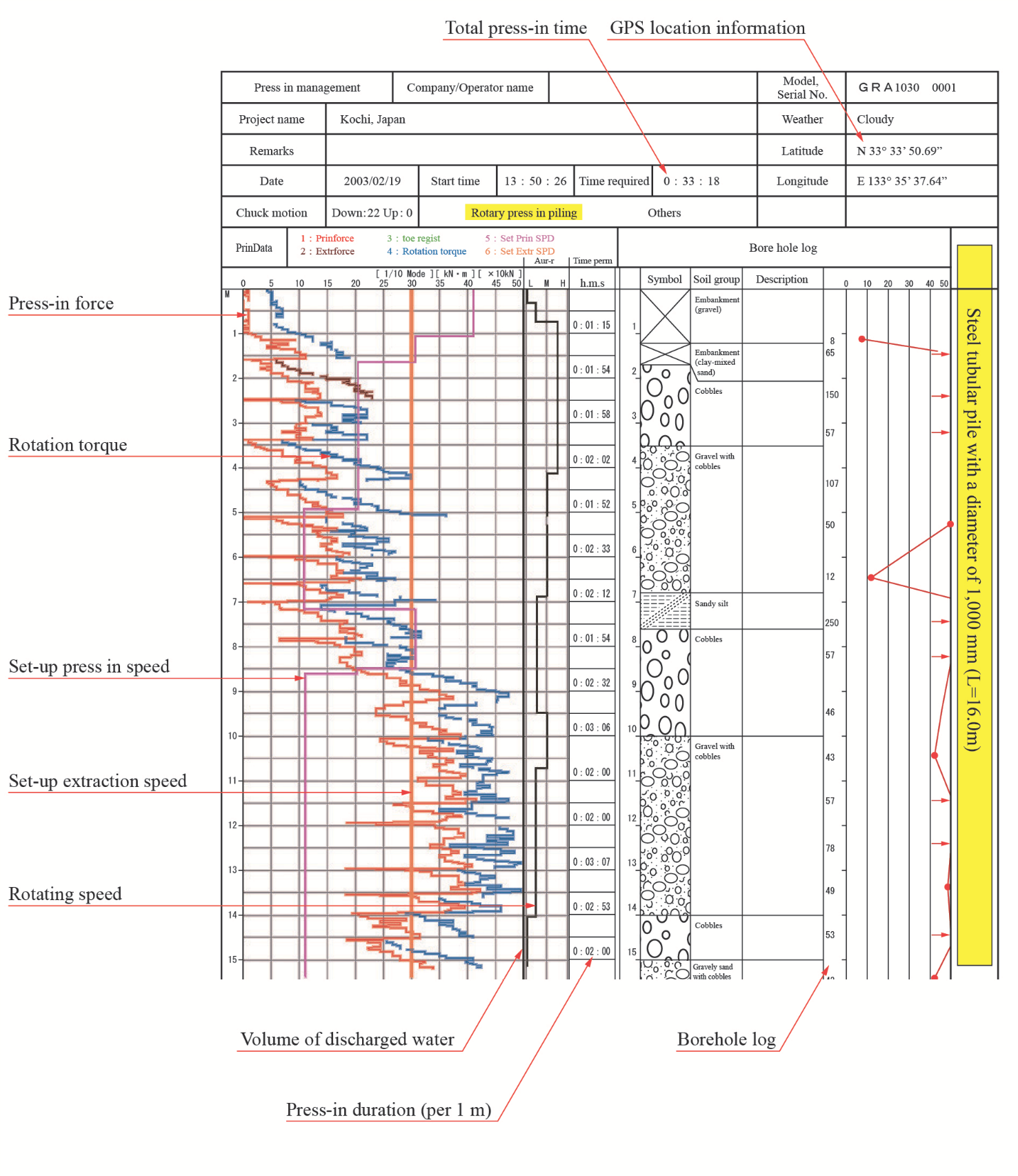
Fig.2. Recorded Press-in force and torque-rotation curves, versus depth, during steel tubular pile installation (IPA, 2021)
3.1 Determination of the undrained cohesion of a purely cohesive soil
The crossed purely cohesive soil layer is of thickness H, and the undrained shear strength Su is assumed to be constant (the friction angle is zero). Application of Eq (5) to the penetration of a tubular pile over a purely cohesive soil of thickness H, with recorded ultimate Press-in force Pult,rec, enables the determination of the undrained cohesion as:
From Fig. 2, consider the recorded torque-rotation curve. The ultimate resisting torque is the sum of two components: the external torque, Mext, and the inner torque, Minn, developed along the outer and the inner lateral areas of the tubular pile, respectively:
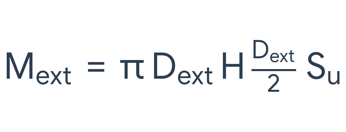 (9a)
(9a)
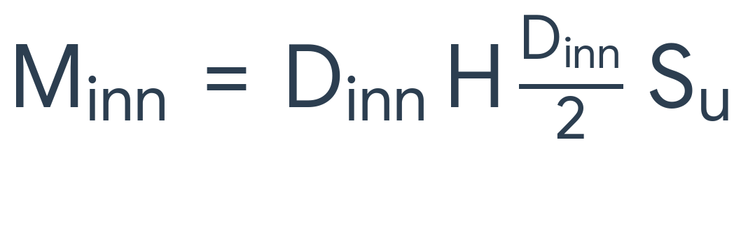 (9b)
(9b)From Eq (8), (9a) and (9b), one obtains:
3.2 Estimation of the friction angle of a cohesionless soil:
Application of Eq (3) to the penetration of a tubular pile over a purely frictional soil (C = 0) of thickness H, the ultimate force is determined from Eq (11):
From Eq (11) one obtains a simple estimation of the friction angle of a purely frictional soil layer of thickness H, by assuming a given value of the coefficient Kp, as an example Kp = 3, and by assuming that: df = j, then, it comes:
In Eq (12) the ultimate force is recorded during the installation of a tubular steel pile, for example, by the Gyro piler method.
In case the torque-rotation curve is considered, from Eq (11), one can determine the ultimate torque by adopting the coefficient of at-rest state of stress: K0 = 0.5 and by assuming that: δ f = φ, then, it comes:
Using the recorded value of the ultimate torque from Press-in data 3n Eq (15), an estimation of the friction angle is possible from Eq (14):
3.3 Estimation of the friction angle of a cohesive-frictional material
3.3.1 Press-in Force
The ultimate force for a cohesive-frictional material is obtained from Eq (3) by substituting dult by H, the layer thickness, and Eq (9); it comes:
Using the proposed method by Bouassida (2024), the friction angle of the cohesive frictional material is estimated by adopting a given value of the cohesion; hence, Eq (15) is rewritten as given by Eq (16):
From Eq (16), one can assume that δ f = φ , then for the given value of C, the suitable value of the friction angle is determined by an iterative procedure where the right and left terms of Eq (16) should be equal with a negligible relative difference.
3.3.2 Press-in torque
In case one considers the at-rest coefficient of earth pressure, the interface friction angle is determined using the recorded ultimate torque value from Eq (17):
4. Analogy between the CST and the steel tubular pile
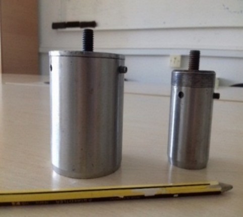
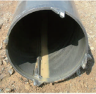
Fig. 3 shows two CST models and the tubular steel pile (IPA, 2021).
 |
 |
| (a) | (b) |
| Fig. 3. The CST models (a) and the steel tubular pile (b) | |
The dimensions of the big-size and small-size CST models are (Bouassida & Azaiez, 2022): length H = 100 mm, H = 70 mm; outer diameter: Dext = 60.5 mm; Dext = 35.2 mm; and inner diameter Di = 57.3 mm; Dinn = 32.4 mm, respectively. The penetration values during tests performed on a remolded Tunis soft clay and compacted quarry sand (Bouassida & Azaiez, 2023) were in the range of 20 to 30 mm. Compared to the dimensions of a steel tube pile (IPA, 2021), the CST models represent a physically scaled model. From these data, the scale factors for dimensions are diameter = 16.5 to 28.5, length = 50, and thickness = 3.7.
5. Investigation of Press-in case study
Table 1. Estimation of shear strength parameters from recorded Press-in data
| Soil type | Recorded Press-in force (kN) | Estimated parameters | Recorded Torque (kN.m) | Estimated parameters |
| Gravel (C = 0) | 10.0 (Kp = 3) | φ = 2.36° | 6.0 (K0 = 0.3) | φ = 26.44° |
| Sandy silt ( φ u = 0) |
70 180 |
Su = 12.45 kPa Su = 32.0 kPa |
16 28 |
Su = 5.72 kPa Su = 10.0 kPa |
| Sandy silt (Su = 10 kPa; Kp = 1; δf = φ) | 70 180 |
φ = 16.7° φ = 69.8° |
16 28 |
Negative value 0.14° |
5.1 Gravel layer assumed as cohesionless soil
Table 1 shows that from the proposed ultimate force value and adopting Kp = 3, the estimated friction angle is unrealistic. However, considering the torque value and the interaction between the steel tube and gravel layer governed by the at-rest state coefficient K0 = 0.3, one obtains a much better estimation of the friction angle j = 26.44°, but it is an underestimated value for gravel material. The best estimation of the gravel friction angle might be obtained using the recently proposed method by Bouassida (2024). This method consists of solving Eq (13) by performing an iterative calculation.
5.2 Silty sandy layer
A realistic assumption for predicting shear strength parameters is when adopting the silty sand as purely cohesive soil. But the cohesive frictional assumption is also studied. Table 1 shows that the use of press-In force and torque values leads to realistic results only when the soil is assumed to be purely cohesive. The realistic estimation of undrained cohesion from the press-in force and torque values is around 10 to 12 kPa, which refers to a soft soil. Contrarily, when assuming the sandy silt as cohesive frictional, one obtains unrealistic values of the friction angle for a given cohesion value of 10 kPa.
6. Concluding remarks
This paper addressed the estimation of shear strength parameters from the data recorded during the installation of a steel tube pile using Press-in technologies. In a preliminary step, the paper summarized a recent method of determination of soil shear strength parameters using the cylindrical shear tool (CST) proposed by Bouassida & Azaiez (2022). Based on the results obtained, especially for purely cohesive, purely frictional and cohesive-frictional soils, and the similarity between a steel tubular pile and the CST, using quasi-static loading, analytical values of the Press-in force and torque are suggested herein. Then, investigating a case study using the Press-in data, the friction angle and undrained cohesion are estimated for two soil layers, namely a gravel and a sandy silt. Interpretation of results showed that the undrained cohesion is acceptable for soft soils. In turn, the determination of the friction angle of purely frictional soils needs careful analysis. Noted that the press-in data are recorded under highly degraded soil and dynamic effects, which were not considered in this primary work. This issue will be addressed soon.
References
Azaiez, D. and Bouassida, M. (2022). An efficient tool to determine undrained shear strength of soft soils. Geotechnical Engineering Journal of the SEAGS & AGSSEA Vol. 53 No.4 December 2022 ISSN 0046-5828.
Bouassida M. and Azaiez, D. (2020). Cylindrical shear Tool. National Patent, Simpro. INNORPI Tunisia. N° 2020/0256.
Bouassida, M., Azaiez, D. and Bouassida, W (2022). “Cylindrical shear tool”. W/O 2022/146238. Priority data /TN2021/050010, 29/12/2020 TN. Simpro Tunisia.
Bouassida, M. & Azaiez, D. (2023). Determination of soil shear parameters. In: Atalar, C., Çinicioğlu, F. (eds) 5th International Conference on New Developments in Soil Mechanics and Geotechnical Engineering. ZM2022. Lecture Notes in Civil Engineering, vol 305. Springer, Cham. https://doi.org/10.1007/978-3-031- 20172-1_10.
Bouassida, M. (2024). Determination of the shear strength of soils using the cylindrical shear tool. Proc. 18th ARCSMGE, Keynote Lecture, Algiers, 06 – 09 October 2024.
IPA (2021). Press-in Retaining structures: A Handbook. 2nd edition, International Press-in Association. Tokyo, Japan.
| << Previous | Newsletter Top | Next >> |