Newsletter Volume 10, Issue 1 March 2025
Directors’ research and development activities
Improving performance and sustainability credentials of existing deep foundations using press-in piling technology
Improving performance and sustainability credentials of existing deep foundations using press-in piling technology
Andrew McNamara
Senior Lecturer, Department of Civil Engineering
City, University of London, London
Senior Lecturer, Department of Civil Engineering
City, University of London, London
Jignasha Panchal
Engineering Manager
A2 Advanced Monitoring, London, United Kingdom
Engineering Manager
A2 Advanced Monitoring, London, United Kingdom
Abstract
The redevelopment of construction sites in large cities now requires the development of solutions to facilitate the reuse of existing deep foundations. New developments tend to be larger and often taller than the previous development, with greater column spacings. This means that the challenge for reusing foundations is that the load-bearing capacity is increased, so developing a way of increasing individual or group pile capacities could prove very beneficial for pile reuse.
This note presents some preliminary tests undertaken to investigate the impact of steel sheet piles installed around an existing bored pile. This composite foundation system was modelled using centrifuge testing, and the results were analyzed using the ICP method.
1. Introduction
Bored piled foundations have been used extensively for about 60 years to accommodate large, heavily loaded buildings and infrastructure. However, as large cities undergo phases of redevelopment, they are beginning to experience problems regarding the obstructions presented by existing deep foundations, lending to the requirement for new, deeper, and larger piled foundations to be installed as the capacity of the existing foundations cannot be verified. This has led to multiple generations of existing foundations being abandoned in the ground, resulting in deep obstructions that are costly and time-consuming to remove if they clash with the specified locations of new foundations.
There is a greater awareness of sustainability due to the climate crisis, which has resulted in clients, funders, and the government scrutinizing the carbon intensity of a project, which can be drastically limited by reducing the volume of concrete specified in a design. Despite the previous piles being integrity tested and the soil consolidation occurring around existing foundations, their capacity can often not be proven or justified as capable of carrying the increased loads of the following development. Given this, there is merit in exploring processes for enhancing the capacity of existing foundations to accommodate such additional loads.
This note describes some model testing undertaken on composite foundations consisting of a central bored pile, representing an existing foundation that may be found on a redevelopment site and comments on the experimental results. The research relates to the provision of sheet piles pressed into the soil around the existing bored pile, and the two foundation elements are integrated into a single load-bearing element through a cast pile cap. The capacity of this enhanced foundation will be compared against a traditional bored pile to provide a normalized load-bearing capacity.
2. Centrifuge model
Centrifuge tests were proposed to model the influence of a composite sheet-piled hybrid foundation on the capacity of an existing bored pile foundation. Speswhite Kaolin clay used in the tests was prepared from a slurry with an initial water content twice its liquid limit. The samples were compressed to a vertical stress of 400kPa, which was then reduced to 200kPa, creating a homogenous sample with an undrained shear strength of around 40kN/m2.
Centrifuge model making
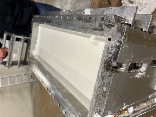
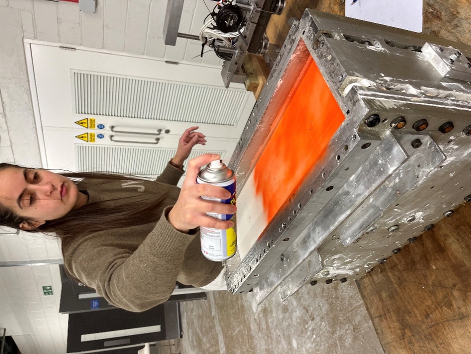
Centrifuge modelling allows researchers to produce relatively small-scale models with compatible prototype soil stresses. Therefore, testing a centrifuge model allows direct scalable conclusions to be made regarding the model and test. The centrifuge model was prepared on the laboratory bench at 1g. The soil sample was removed from the consolidation press, and the top was trimmed to reduce the clay depth (Fig. 1) to a predetermined level that would permit the use of the loading apparatus. A Perspex template, as shown in Fig. 2, was positioned on the clay surface, with guides that permitted the position of the pile bores to be marked in precise locations. The surface of the clay sample was sealed, as shown in Fig. 3.
Rotary bored pile installation
Three piled foundation models were installed as part of this experiment. The foundations were positioned equidistant from one another, with sufficient distance to the walls of the model container to minimize the influence of edge distance effects.
The diameter of the model's existing rotary bored piles was 16mm, representative of a 0.8m diameter pile at the prototype scale. The aluminum piles were roughened to provide soil/pile interface friction reasonably representative of that created with a concrete bored pile.
Each pile bore was excavated using a thin-walled stainless steel tube cutter inserted through the guides and gently rotated at depth, ensuring that a complete plug of soil was effectively sheared. The solid aluminum model piles were inserted into each borehole when the three pile bores were formed. All the piles were bored to a depth of 180mm, ensuring that a minimum 5D clear spacing existed below the pile toe to minimize edge distance effects at the model's base.
Sheet-piled wall installation
Installation of the sheet pile enhancement to the bored piles was carried out in which square plan foundations, manufactured from a continuous length of 0.8mm thick corrugated steel sheet, were folded and welded along one edge; this is equivalent to a 2.5m x 2.5m sheet pile at the prototype scale. The sheet pile inclusion was positioned concentrically about the model pile and embedded by gently pressing into position, as shown in Fig. 4.
Two sheet pile lengths were used to investigate the impact of sheet pile embedment on the overall capacity enhancement. The sheet pile wall embedment depths were 60mm and 120mm, respectively, representative of 33% and 67% of the total rotary bored pile length, equivalent to 3m and 6m, respectively, at the prototype scale.
Following the installation of the sheet piles, a resin pile cap was poured at the soil surface level, simulating the pile cap that would be needed to provide a connection. This allowed the bored and sheet pile combination to act compositely under load.
The reference pile was not enhanced with embedded sheet piles, so a sheet pile perimeter was placed at the soil surface to create a surface pile cap identical in plan dimensions to the embedded sheet piles; note that this was not embedded into the soil to allow direct comparisons between each test specimen.
Preparation of the model prior to loading
The bored piles protruded above the level of the sheet-piled walls, and the area between the sheet piles and the bored pile was filled with a fast-cast polyurethane resin used for intricate moldings (McNamara, 2001; Gorasia and McNamara, 2016).
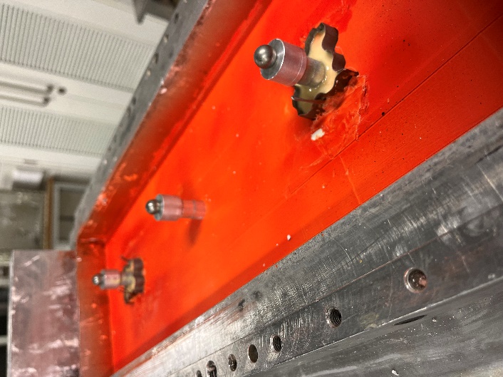
A machined aluminum loading cap was positioned centrally on top of each bored pile. A centrally reamed countersunk bore was machined within each loading cap, which allowed for a steel ball bearing to be placed. A force plate comprises three load cells sandwiched between two aluminum plates. This arrangement ensured that the piles were loaded axially, without any eccentricity, as shown in Fig. 5.
3. Pile loading
The model was placed on the centrifuge and accelerated to 50g. There was consequently no period of consolidation, so the loading phase was carried out immediately after the centrifuge reached 50g. The piles were loaded simultaneously through a single-beam motorized actuator at a rate of 1mm/minute, shown schematically in Fig. 6, which allowed all foundations to be loaded simultaneously. Displacement of the foundations was determined from the measurement of time using the data logging computer.
The foundations were loaded until the load increase with time became negligible, suggesting peak capacity had been reached. However, the sheet pile enhanced foundations exhibited such significant additional capacity that it was not possible to determine their ultimate capacity with the loading apparatus that had been used.
4. Results
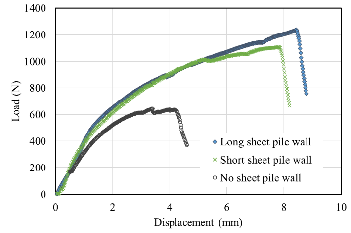
The load-settlement curves for each of the three model foundation tests were recorded during the test and are plotted in Fig. 7.
Generally, the load-displacement curves for each of the tests follow an expected trend. The enhanced foundations appeared to be equally stiff during the early part of loading, and the pile stiffness gradually reduced after approximately 1mm of settlement. As further load was applied, the composite bored and sheet-piled wall foundations exhibited a stiffer response, and this continued well beyond the failure load of the unenhanced foundation.
The baseline bored pile displays definitive failure at a load of approximately 600N at a settlement of 3mm, after which it continues to fail, bearing a constant load.
In comparison, the composite sheet-piled foundation arrangements proved capable of carrying significantly higher loads. The short sheet-piled wall-enhanced foundation reached an applied load of 1100N, whilst the deeper sheet-piled wall reached loads in excess of 1230N without overcoming full resistance.
5. Discussion
The results from the centrifuge model pile load test demonstrate the potential benefit of providing a connection between rotary bored piles and a sheet piled wall to generate a composite-acting piled foundation system. The data clearly suggests that forming a composite foundation could offer significant benefits over individual piles and it appears that the sheet piles do not need to be particularly deeply embedded to make a useful improvement in bearing capacity.
The piles were exhumed, and the connection between the central pile and pile cap remained intact, suggesting that the combined foundations worked as intended.
The loading behavior and bearing capacity of this composite foundation can be described using the ICP design methods (Jardine et al., 2005). This method describes the mechanism whereby the composite sheet piled foundations can be analyzed as open-ended tubular piles, where end-bearing resistance can be reduced by 50% to account for the plugging effect at the base of the pile, whilst the rest of the composite pile benefits from the additional shaft capacity afforded to the system by the sheet piled wall.
6. Analysis
The ultimate bearing capacity of a foundation system is the sum of the shaft friction and end bearing. Owing to the construction and installation method of the composite pile, the sheet-piled foundation element is analyzed using the ICP design method (Jardine et al., 2005), where the sheet piles are considered open-ended tubular piles.
As such, the end bearing resistance mobilized by the sheet piled wall of the composite foundation is recommended to be reduced by a factor of two to account for plugging effects. This method for calculating the capacity of tubular piles, particularly in offshore applications, has proven incredibly successful and accurate. Previous research has also been undertaken using this method of sheet-piled groups (Panchal et al., 2018), and it has been shown to provide a high degree of accuracy when compared with model test results.
Q(ult) = Qb + Qs (1)
Qs = EAs Su α (2)
Qb = EAb (Nc Su + γ H) (3)
Qb,sheet = [ EAb (Nc Su + γ H) ] / 2 (4)
A hand shear vane was used to measure Su, the average soil undrained shear strength, immediately after each test, giving a reading of 40kPa. The bearing capacity factor (Nc) was taken as 9 for deep piles γ A bulk unit weight of 17kN/m3 was used. L is the pile length, and α is the adhesion factor. The ultimate bearing capacity of the plain foundation was calculated with an estimated capacity of 640N.
In comparison, the foundations with both a bored pile and sheet piled wall benefit from both foundation systems. For instance, the ultimate capacities of these piles have been derived by taking end bearing and shaft friction from the bore pile beneath the toe level of the sheet-piled wall. In addition, the shaft friction of the full sheet piled wall is used, and the end-bearing resistance of the wall system is reduced by half before being accounted for in the capacity of the system.
Each foundation system was estimated using the ICP method to check whether the capacity and the short sheet piled wall could carry 1170N of axial load, and the deep sheet pile was expected to carry 1400N of axial load.
The results demonstrated that the estimated foundation capacity, calculated using conventional pile capacity calculations and the ICP method accounting for a reduction of end bearing for a sheet piled wall system, gives a prediction that is within a 10% envelope of the measured ultimate capacity, as shown in Fig. 8. This demonstrates that the ICP method is a very useful and practical tool for estimating the capacity of a press-in sheet piled wall arranged in a group formation.
Note that the ultimate capacity of both composite sheet piled wall foundation systems was interpolated from the load settlement plots since the piles had not failed during the centrifuge test.
7. Sustainability benefits of sheet piled technology
The environmental and economic impact of coring out existing reinforced concrete piles, only to replace them with slightly larger or deeper concrete piles is notable. The emissions are a contribution of the following activities, but are not limited to:
Further to the embodied carbon emissions, the social implications of replacing existing foundations can be significant, particularly in urban environments where demolition and construction works can have a negative prolonged impact on local communities. However, if particular construction practices were adopted to minimize single-use structures and the excessive consumption of raw materials, the overall sustainability rating of construction projects could be improved.
Using Giken's “Five Construction Principles” allows designers and contractors a quantifiable method of evaluating the impacts of a particular construction solution. A simple carbon analysis has been undertaken using the EFFC DFI Carbon Calculator (2023), which compares the impact of coring and replacing deep-bore foundations against the installation of a composite foundation using sheet piles around an existing deep-bore foundation.
The EFFC DFI Carbon Calculator is frequently used in European countries to quantify the embodied carbon contained within their foundation solution. It considers program, energy consumption, raw materials, transportation, etc. and the emissions factors of various construction materials.
An example calculation has been prepared to demonstrate the potential carbon impacts of the various construction techniques using the centrifuge model test at prototype scale. Fig. 9 presents the embodied carbon which corresponds to; a baseline pile (i.e. an existing pile that was historically installed but excludes the emissions from the plant that were used to construct the pile); a replacement pile (i.e. coring of an existing pile and replacement with a new pile design); the Sheet pile 3m pile (existing bored pile with 3m deep embedded sheet piles); and the Sheet pile 6m (existing bored pile with 6m deep embedded sheets).
The calculations are based on assumed concrete mix designs, bored pile reinforcement content and construction programs. However, the results generally show that the embodied carbon associated with a shallow embedded sheet pile around an existing bored pile is 40% lower than that of a replacement bored pile. A deeper sheet pile will result in a higher embodied carbon content than a replacement bored pile.
Fig. 10 presents two plots, which give the measured capacity against the embodied carbon, and a normalized plot, which shows the carbon intensity per N for each construction technique. The graph demonstrates that the replacement pile has the highest carbon intensity per N of capacity, whereas the sheet pile methods have considerably lower carbon intensities. The graph also demonstrates that doubling the length of the sheet pile only increases the carbon intensity by 50%. Of course, more detailed analyses could be undertaken on full-scale tests to validate these normalized values.
It is important to note that the benefit of the sheet-piled system is that, unlike the bored pile system, no waste is generated from the installation of the sheet piles. Furthermore, the system follows the principles of circular economy, as the sheet piles can later be extracted with minimal impact, and the sheets can be reused or recycled with nominal energy expended on reprocessing the materials.
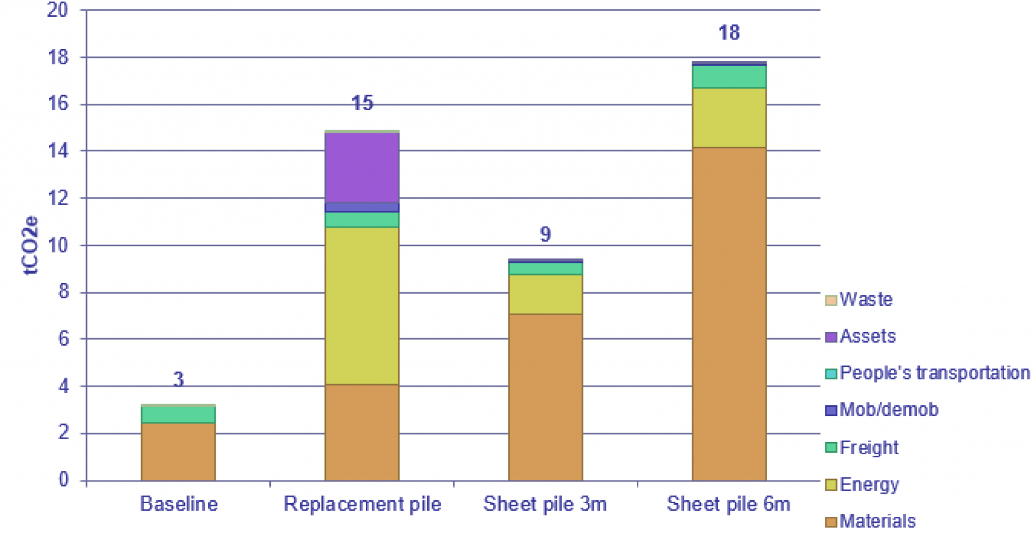
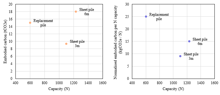 Fig. 10. EFFC Carbon comparison of a coring/replacement bored foundation vs. a composite sheet piled wall around an existing foundation
8. Concluding remarks
Three model foundations in over consolidated clay was loaded simultaneously at 50g in a centrifuge. A baseline model foundation was compared against two of the hybrid foundations which comprised a central pile surrounded by sheet piles of differing embedment depth. The use of sheet pile enhancements to the single pile foundations proved effective in increasing capacity at large strains and appears to show benefits at small strains.
The ICP method, in combination with Terzaghi’s pile capacity formulae, was used to estimate the capacity of the composite sheet-piled foundation. The estimations were compared against the measured and interpolated ultimate capacities of the piles, and the results were in very good agreement, such that the measured capacity was within 10% of the predicted capacity.
At ultimate capacity, even the shallow embedded sheet piles significantly increase capacity, suggesting that further exploration of this method may be merited.
The EFFC DFI Carbon Calculator was used to measure the sustainability and embodied carbon of these centrifuge model tests based on assumed material properties. In general, the results have shown that the sheet-piled hybrid pile system is a less carbon-intensive construction method for the additional capacity generated by the system.
Further full-scale testing would be beneficial to validate the method of calculating the capacity of the hybrid foundation system and cross-check it against the carbon calculations to better understand the impact of various construction techniques on sustainability in the industry.
References
Osterberg, J. O. “A new simplified method for load testing drilled piles” Foundation Drilling, 1984, 23 (6): 911.
Osterberg, J. O. “The Osterberg load test method for bored and driven pile: The first ten years” Proc. 7th Inst Conf. and Exhibition on Piling and Deep Foundations. Vienna, Austria. June 15-17, Deep Foundation Institute, Englewood Cliffs, N.J., 1.28.1-1.28.11. 1998.
Fellenius, B., Altaee, A., Kulesza, R. and Hayes, J.: O-cell testing and FE analysis of a 28-m-deep barrette pile Manila, Philippines, ASCE Journal of Geotechnical and Geoenvironmental Engineering, Vol. 125 No. 7 (July 1999), 566-575.Osterberg, J. O. “A new simplified method for load testing drilled piles” Foundation Drilling, 1984, 23 (6): 911.
Gong Weiming, Dai Guoliang, Jiang Yongsheng, Xue Guoya. Theory and practice of self-balanced loading test for pile bearing capacity Journal of Building Structures, 2002, 23 (1): 8288.Osterberg, J. O. “A new simplified method for load testing drilled piles” Foundation Drilling, 1984, 23 (6): 911.
Konder, R. L., Zelasko, J. S. “A hyperbolic stress-strain relationship for sands,” Proceedings of the 2nd Pan-American Conference on Soil Mechanics and Foundation Engineering, Vol. 1, Brazil (1963) p. 289.
Lee J S, Park Y H. Equivalent pile load-head settlement curve using a bi-directional pile load test. Computers and Geotechnics, 2008, 35 (2):124133.
Press, W. H., Vetterling, W. T., Teukolsky, S. A., & Flannery, B. P. (1988). Numerical recipes. Cambridge University Press, London, England.
Panchal, J. P., McNamara, A. M. & Goodey, R.J. (2018). Influence of geometry on the bearing capacity of sheet piled foundations. In: McNamara, A. M., Divall, S., Goodey, R.J., Taylor, N, Stallebrass, S. E. & Panchal, J. P. (Eds.), Physical Modelling in Geotechnics: Proceedings of the 9th International Conference on Physical Modelling in Geotechnics (ICPMG 2018), July 17-20, 2018, London, United Kingdom. (pp. 1395-1400).
EFFC. (2023) EFFC/DFI Carbon Calculator.
The redevelopment of construction sites in large cities now requires the development of solutions to facilitate the reuse of existing deep foundations. New developments tend to be larger and often taller than the previous development, with greater column spacings. This means that the challenge for reusing foundations is that the load-bearing capacity is increased, so developing a way of increasing individual or group pile capacities could prove very beneficial for pile reuse.
This note presents some preliminary tests undertaken to investigate the impact of steel sheet piles installed around an existing bored pile. This composite foundation system was modelled using centrifuge testing, and the results were analyzed using the ICP method.
1. Introduction
Bored piled foundations have been used extensively for about 60 years to accommodate large, heavily loaded buildings and infrastructure. However, as large cities undergo phases of redevelopment, they are beginning to experience problems regarding the obstructions presented by existing deep foundations, lending to the requirement for new, deeper, and larger piled foundations to be installed as the capacity of the existing foundations cannot be verified. This has led to multiple generations of existing foundations being abandoned in the ground, resulting in deep obstructions that are costly and time-consuming to remove if they clash with the specified locations of new foundations.
There is a greater awareness of sustainability due to the climate crisis, which has resulted in clients, funders, and the government scrutinizing the carbon intensity of a project, which can be drastically limited by reducing the volume of concrete specified in a design. Despite the previous piles being integrity tested and the soil consolidation occurring around existing foundations, their capacity can often not be proven or justified as capable of carrying the increased loads of the following development. Given this, there is merit in exploring processes for enhancing the capacity of existing foundations to accommodate such additional loads.
This note describes some model testing undertaken on composite foundations consisting of a central bored pile, representing an existing foundation that may be found on a redevelopment site and comments on the experimental results. The research relates to the provision of sheet piles pressed into the soil around the existing bored pile, and the two foundation elements are integrated into a single load-bearing element through a cast pile cap. The capacity of this enhanced foundation will be compared against a traditional bored pile to provide a normalized load-bearing capacity.
2. Centrifuge model
Centrifuge tests were proposed to model the influence of a composite sheet-piled hybrid foundation on the capacity of an existing bored pile foundation. Speswhite Kaolin clay used in the tests was prepared from a slurry with an initial water content twice its liquid limit. The samples were compressed to a vertical stress of 400kPa, which was then reduced to 200kPa, creating a homogenous sample with an undrained shear strength of around 40kN/m2.
Centrifuge model making
Centrifuge modelling allows researchers to produce relatively small-scale models with compatible prototype soil stresses. Therefore, testing a centrifuge model allows direct scalable conclusions to be made regarding the model and test. The centrifuge model was prepared on the laboratory bench at 1g. The soil sample was removed from the consolidation press, and the top was trimmed to reduce the clay depth (Fig. 1) to a predetermined level that would permit the use of the loading apparatus. A Perspex template, as shown in Fig. 2, was positioned on the clay surface, with guides that permitted the position of the pile bores to be marked in precise locations. The surface of the clay sample was sealed, as shown in Fig. 3.
Rotary bored pile installation
Three piled foundation models were installed as part of this experiment. The foundations were positioned equidistant from one another, with sufficient distance to the walls of the model container to minimize the influence of edge distance effects.
The diameter of the model's existing rotary bored piles was 16mm, representative of a 0.8m diameter pile at the prototype scale. The aluminum piles were roughened to provide soil/pile interface friction reasonably representative of that created with a concrete bored pile.
Each pile bore was excavated using a thin-walled stainless steel tube cutter inserted through the guides and gently rotated at depth, ensuring that a complete plug of soil was effectively sheared. The solid aluminum model piles were inserted into each borehole when the three pile bores were formed. All the piles were bored to a depth of 180mm, ensuring that a minimum 5D clear spacing existed below the pile toe to minimize edge distance effects at the model's base.
Sheet-piled wall installation
Installation of the sheet pile enhancement to the bored piles was carried out in which square plan foundations, manufactured from a continuous length of 0.8mm thick corrugated steel sheet, were folded and welded along one edge; this is equivalent to a 2.5m x 2.5m sheet pile at the prototype scale. The sheet pile inclusion was positioned concentrically about the model pile and embedded by gently pressing into position, as shown in Fig. 4.
Two sheet pile lengths were used to investigate the impact of sheet pile embedment on the overall capacity enhancement. The sheet pile wall embedment depths were 60mm and 120mm, respectively, representative of 33% and 67% of the total rotary bored pile length, equivalent to 3m and 6m, respectively, at the prototype scale.
Following the installation of the sheet piles, a resin pile cap was poured at the soil surface level, simulating the pile cap that would be needed to provide a connection. This allowed the bored and sheet pile combination to act compositely under load.
The reference pile was not enhanced with embedded sheet piles, so a sheet pile perimeter was placed at the soil surface to create a surface pile cap identical in plan dimensions to the embedded sheet piles; note that this was not embedded into the soil to allow direct comparisons between each test specimen.
Preparation of the model prior to loading
The bored piles protruded above the level of the sheet-piled walls, and the area between the sheet piles and the bored pile was filled with a fast-cast polyurethane resin used for intricate moldings (McNamara, 2001; Gorasia and McNamara, 2016).
A machined aluminum loading cap was positioned centrally on top of each bored pile. A centrally reamed countersunk bore was machined within each loading cap, which allowed for a steel ball bearing to be placed. A force plate comprises three load cells sandwiched between two aluminum plates. This arrangement ensured that the piles were loaded axially, without any eccentricity, as shown in Fig. 5.
3. Pile loading
The model was placed on the centrifuge and accelerated to 50g. There was consequently no period of consolidation, so the loading phase was carried out immediately after the centrifuge reached 50g. The piles were loaded simultaneously through a single-beam motorized actuator at a rate of 1mm/minute, shown schematically in Fig. 6, which allowed all foundations to be loaded simultaneously. Displacement of the foundations was determined from the measurement of time using the data logging computer.
The foundations were loaded until the load increase with time became negligible, suggesting peak capacity had been reached. However, the sheet pile enhanced foundations exhibited such significant additional capacity that it was not possible to determine their ultimate capacity with the loading apparatus that had been used.
 |
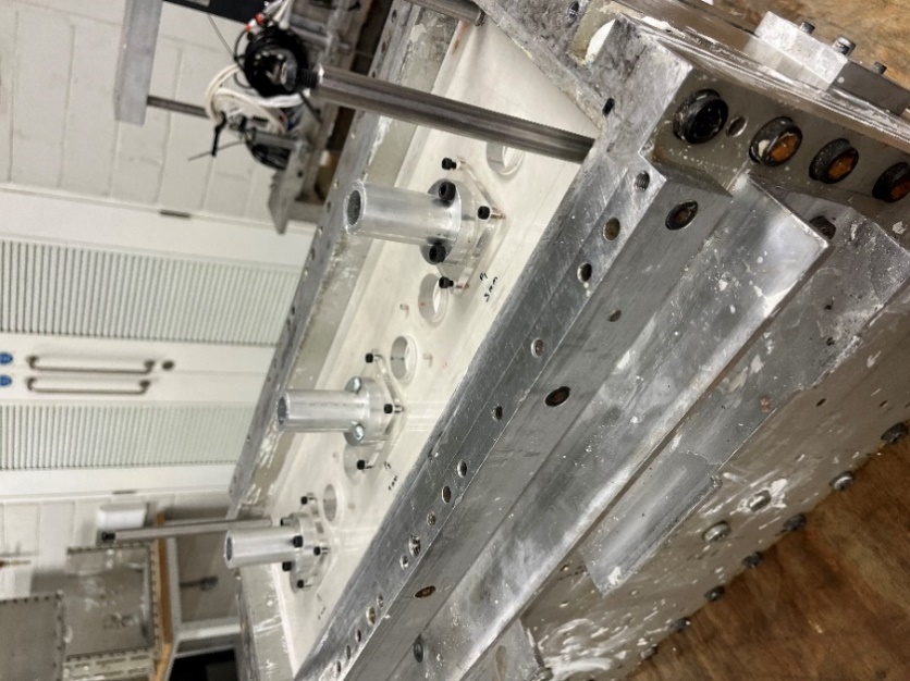 |
| Fig. 1. Trimming the clay surface to the correct level | Fig. 2. Method of positioning piles. |
 |
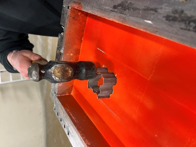 |
| Fig. 3. Sealing the surface of the clay model | Fig. 4. Installing the embedded sheet piled wall |
 |
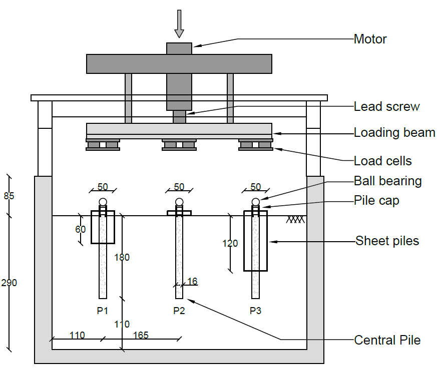 |
| Fig. 5. Foundations during model making | Fig. 6. Arrangement of loading apparatus on model |
4. Results
The load-settlement curves for each of the three model foundation tests were recorded during the test and are plotted in Fig. 7.
Generally, the load-displacement curves for each of the tests follow an expected trend. The enhanced foundations appeared to be equally stiff during the early part of loading, and the pile stiffness gradually reduced after approximately 1mm of settlement. As further load was applied, the composite bored and sheet-piled wall foundations exhibited a stiffer response, and this continued well beyond the failure load of the unenhanced foundation.
The baseline bored pile displays definitive failure at a load of approximately 600N at a settlement of 3mm, after which it continues to fail, bearing a constant load.
In comparison, the composite sheet-piled foundation arrangements proved capable of carrying significantly higher loads. The short sheet-piled wall-enhanced foundation reached an applied load of 1100N, whilst the deeper sheet-piled wall reached loads in excess of 1230N without overcoming full resistance.
Fig. 7. Load-settlement curves
5. Discussion
The results from the centrifuge model pile load test demonstrate the potential benefit of providing a connection between rotary bored piles and a sheet piled wall to generate a composite-acting piled foundation system. The data clearly suggests that forming a composite foundation could offer significant benefits over individual piles and it appears that the sheet piles do not need to be particularly deeply embedded to make a useful improvement in bearing capacity.
The piles were exhumed, and the connection between the central pile and pile cap remained intact, suggesting that the combined foundations worked as intended.
The loading behavior and bearing capacity of this composite foundation can be described using the ICP design methods (Jardine et al., 2005). This method describes the mechanism whereby the composite sheet piled foundations can be analyzed as open-ended tubular piles, where end-bearing resistance can be reduced by 50% to account for the plugging effect at the base of the pile, whilst the rest of the composite pile benefits from the additional shaft capacity afforded to the system by the sheet piled wall.
6. Analysis
The ultimate bearing capacity of a foundation system is the sum of the shaft friction and end bearing. Owing to the construction and installation method of the composite pile, the sheet-piled foundation element is analyzed using the ICP design method (Jardine et al., 2005), where the sheet piles are considered open-ended tubular piles.
As such, the end bearing resistance mobilized by the sheet piled wall of the composite foundation is recommended to be reduced by a factor of two to account for plugging effects. This method for calculating the capacity of tubular piles, particularly in offshore applications, has proven incredibly successful and accurate. Previous research has also been undertaken using this method of sheet-piled groups (Panchal et al., 2018), and it has been shown to provide a high degree of accuracy when compared with model test results.
Q(ult) = Qb + Qs (1)
Qs = EAs Su α (2)
Qb = EAb (Nc Su + γ H) (3)
Qb,sheet = [ EAb (Nc Su + γ H) ] / 2 (4)
A hand shear vane was used to measure Su, the average soil undrained shear strength, immediately after each test, giving a reading of 40kPa. The bearing capacity factor (Nc) was taken as 9 for deep piles γ A bulk unit weight of 17kN/m3 was used. L is the pile length, and α is the adhesion factor. The ultimate bearing capacity of the plain foundation was calculated with an estimated capacity of 640N.
In comparison, the foundations with both a bored pile and sheet piled wall benefit from both foundation systems. For instance, the ultimate capacities of these piles have been derived by taking end bearing and shaft friction from the bore pile beneath the toe level of the sheet-piled wall. In addition, the shaft friction of the full sheet piled wall is used, and the end-bearing resistance of the wall system is reduced by half before being accounted for in the capacity of the system.
Each foundation system was estimated using the ICP method to check whether the capacity and the short sheet piled wall could carry 1170N of axial load, and the deep sheet pile was expected to carry 1400N of axial load.
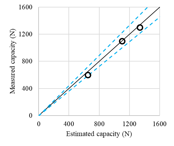
The results demonstrated that the estimated foundation capacity, calculated using conventional pile capacity calculations and the ICP method accounting for a reduction of end bearing for a sheet piled wall system, gives a prediction that is within a 10% envelope of the measured ultimate capacity, as shown in Fig. 8. This demonstrates that the ICP method is a very useful and practical tool for estimating the capacity of a press-in sheet piled wall arranged in a group formation.
Note that the ultimate capacity of both composite sheet piled wall foundation systems was interpolated from the load settlement plots since the piles had not failed during the centrifuge test.
Fig. 8. Comparison between estimate and measured capacities with a 10% margin
7. Sustainability benefits of sheet piled technology
The environmental and economic impact of coring out existing reinforced concrete piles, only to replace them with slightly larger or deeper concrete piles is notable. The emissions are a contribution of the following activities, but are not limited to:
- Plant fuel emissions during mobilization and coring activities
- Transport of waste material off-site
- Processing of waste concrete material
- Emissions to produce fresh concrete and reinforcement
- Emissions associated with the construction of new foundation structures
Further to the embodied carbon emissions, the social implications of replacing existing foundations can be significant, particularly in urban environments where demolition and construction works can have a negative prolonged impact on local communities. However, if particular construction practices were adopted to minimize single-use structures and the excessive consumption of raw materials, the overall sustainability rating of construction projects could be improved.
Using Giken's “Five Construction Principles” allows designers and contractors a quantifiable method of evaluating the impacts of a particular construction solution. A simple carbon analysis has been undertaken using the EFFC DFI Carbon Calculator (2023), which compares the impact of coring and replacing deep-bore foundations against the installation of a composite foundation using sheet piles around an existing deep-bore foundation.
The EFFC DFI Carbon Calculator is frequently used in European countries to quantify the embodied carbon contained within their foundation solution. It considers program, energy consumption, raw materials, transportation, etc. and the emissions factors of various construction materials.
An example calculation has been prepared to demonstrate the potential carbon impacts of the various construction techniques using the centrifuge model test at prototype scale. Fig. 9 presents the embodied carbon which corresponds to; a baseline pile (i.e. an existing pile that was historically installed but excludes the emissions from the plant that were used to construct the pile); a replacement pile (i.e. coring of an existing pile and replacement with a new pile design); the Sheet pile 3m pile (existing bored pile with 3m deep embedded sheet piles); and the Sheet pile 6m (existing bored pile with 6m deep embedded sheets).
The calculations are based on assumed concrete mix designs, bored pile reinforcement content and construction programs. However, the results generally show that the embodied carbon associated with a shallow embedded sheet pile around an existing bored pile is 40% lower than that of a replacement bored pile. A deeper sheet pile will result in a higher embodied carbon content than a replacement bored pile.
Fig. 10 presents two plots, which give the measured capacity against the embodied carbon, and a normalized plot, which shows the carbon intensity per N for each construction technique. The graph demonstrates that the replacement pile has the highest carbon intensity per N of capacity, whereas the sheet pile methods have considerably lower carbon intensities. The graph also demonstrates that doubling the length of the sheet pile only increases the carbon intensity by 50%. Of course, more detailed analyses could be undertaken on full-scale tests to validate these normalized values.
It is important to note that the benefit of the sheet-piled system is that, unlike the bored pile system, no waste is generated from the installation of the sheet piles. Furthermore, the system follows the principles of circular economy, as the sheet piles can later be extracted with minimal impact, and the sheets can be reused or recycled with nominal energy expended on reprocessing the materials.
Fig. 9. EFFC Carbon comparison of a coring/replacement bored foundation vs. a composite sheet piled wall around an existing foundation
8. Concluding remarks
Three model foundations in over consolidated clay was loaded simultaneously at 50g in a centrifuge. A baseline model foundation was compared against two of the hybrid foundations which comprised a central pile surrounded by sheet piles of differing embedment depth. The use of sheet pile enhancements to the single pile foundations proved effective in increasing capacity at large strains and appears to show benefits at small strains.
The ICP method, in combination with Terzaghi’s pile capacity formulae, was used to estimate the capacity of the composite sheet-piled foundation. The estimations were compared against the measured and interpolated ultimate capacities of the piles, and the results were in very good agreement, such that the measured capacity was within 10% of the predicted capacity.
At ultimate capacity, even the shallow embedded sheet piles significantly increase capacity, suggesting that further exploration of this method may be merited.
The EFFC DFI Carbon Calculator was used to measure the sustainability and embodied carbon of these centrifuge model tests based on assumed material properties. In general, the results have shown that the sheet-piled hybrid pile system is a less carbon-intensive construction method for the additional capacity generated by the system.
Further full-scale testing would be beneficial to validate the method of calculating the capacity of the hybrid foundation system and cross-check it against the carbon calculations to better understand the impact of various construction techniques on sustainability in the industry.
References
Osterberg, J. O. “A new simplified method for load testing drilled piles” Foundation Drilling, 1984, 23 (6): 911.
Osterberg, J. O. “The Osterberg load test method for bored and driven pile: The first ten years” Proc. 7th Inst Conf. and Exhibition on Piling and Deep Foundations. Vienna, Austria. June 15-17, Deep Foundation Institute, Englewood Cliffs, N.J., 1.28.1-1.28.11. 1998.
Fellenius, B., Altaee, A., Kulesza, R. and Hayes, J.: O-cell testing and FE analysis of a 28-m-deep barrette pile Manila, Philippines, ASCE Journal of Geotechnical and Geoenvironmental Engineering, Vol. 125 No. 7 (July 1999), 566-575.Osterberg, J. O. “A new simplified method for load testing drilled piles” Foundation Drilling, 1984, 23 (6): 911.
Gong Weiming, Dai Guoliang, Jiang Yongsheng, Xue Guoya. Theory and practice of self-balanced loading test for pile bearing capacity Journal of Building Structures, 2002, 23 (1): 8288.Osterberg, J. O. “A new simplified method for load testing drilled piles” Foundation Drilling, 1984, 23 (6): 911.
Konder, R. L., Zelasko, J. S. “A hyperbolic stress-strain relationship for sands,” Proceedings of the 2nd Pan-American Conference on Soil Mechanics and Foundation Engineering, Vol. 1, Brazil (1963) p. 289.
Lee J S, Park Y H. Equivalent pile load-head settlement curve using a bi-directional pile load test. Computers and Geotechnics, 2008, 35 (2):124133.
Press, W. H., Vetterling, W. T., Teukolsky, S. A., & Flannery, B. P. (1988). Numerical recipes. Cambridge University Press, London, England.
Panchal, J. P., McNamara, A. M. & Goodey, R.J. (2018). Influence of geometry on the bearing capacity of sheet piled foundations. In: McNamara, A. M., Divall, S., Goodey, R.J., Taylor, N, Stallebrass, S. E. & Panchal, J. P. (Eds.), Physical Modelling in Geotechnics: Proceedings of the 9th International Conference on Physical Modelling in Geotechnics (ICPMG 2018), July 17-20, 2018, London, United Kingdom. (pp. 1395-1400).
EFFC. (2023) EFFC/DFI Carbon Calculator.
| << Previous | Newsletter Top | Next >> |