Newsletter Volume 11, Issue 2 June 2026
Assessing the Bearing Capacity of Urban Waterborne Piled Structures in Terms of Operation Conditions and Service Life
Odessa National Maritime University, Ukraine
1. Introduction
In many European cities located on seas and rivers, waterborne infrastructure is made with piled constructions, which have been erected, basically, in the begin-ning or in the second half of the last century. One of the most widespread con-structive decisions of seaports was piled embankments and quays, whose share in some large ports exceeds 50 % of the total length of berths. Some typical de-signs of piled waterborne structures supported by concrete and steel tubular piles are presented in Fig. 1 and 2, respectively.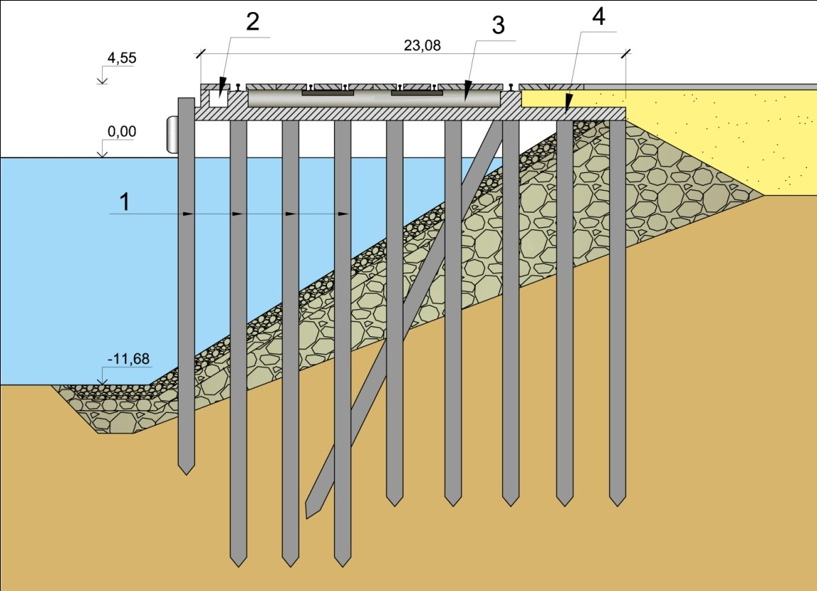 |
|
Fig. 1. Embankment structure |
Prismatic reinforced concrete piles are precast, uniform-section driven founda-tion elements, widely used to transfer structural loads to deeper, firmer soil lay-ers through end-bearing and friction. These are precast piles, often pre-stressed, featuring a constant cross-section (prismatic). They are typically square, though they can be circular, with lengths that can be adapted to specific requirements.
 |
|
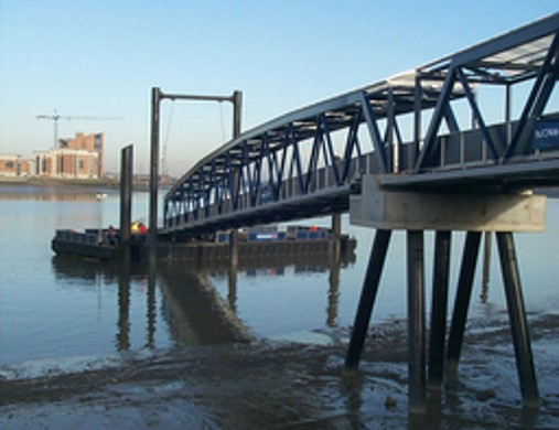
Fig. 2. Bridge berthing structure on steel tubular piles |
Steel tubular piles are high-strength cylindrical pipes driven into the ground to provide deep-foundation support for heavy, lateral, or axial loads in challenging soil, marine, or urban environments.
2. Problems of piled structures maintenance
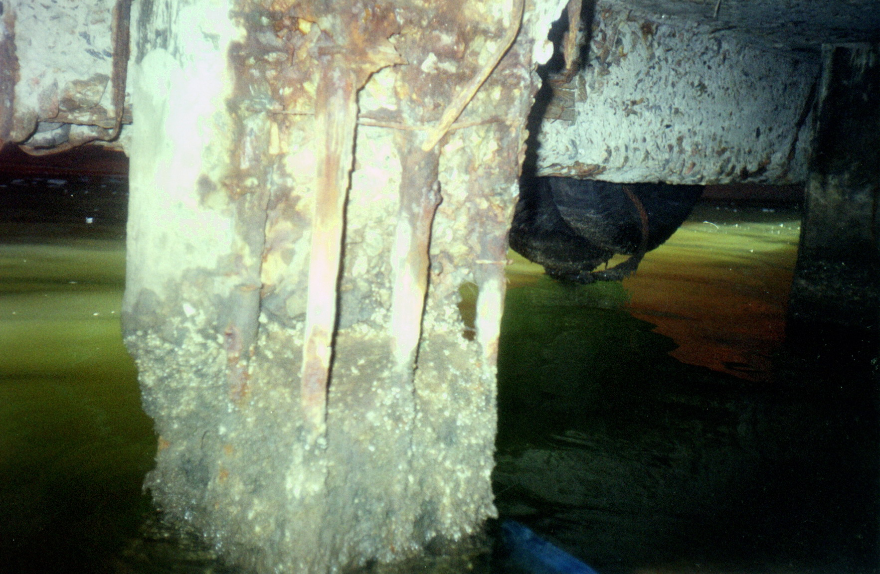
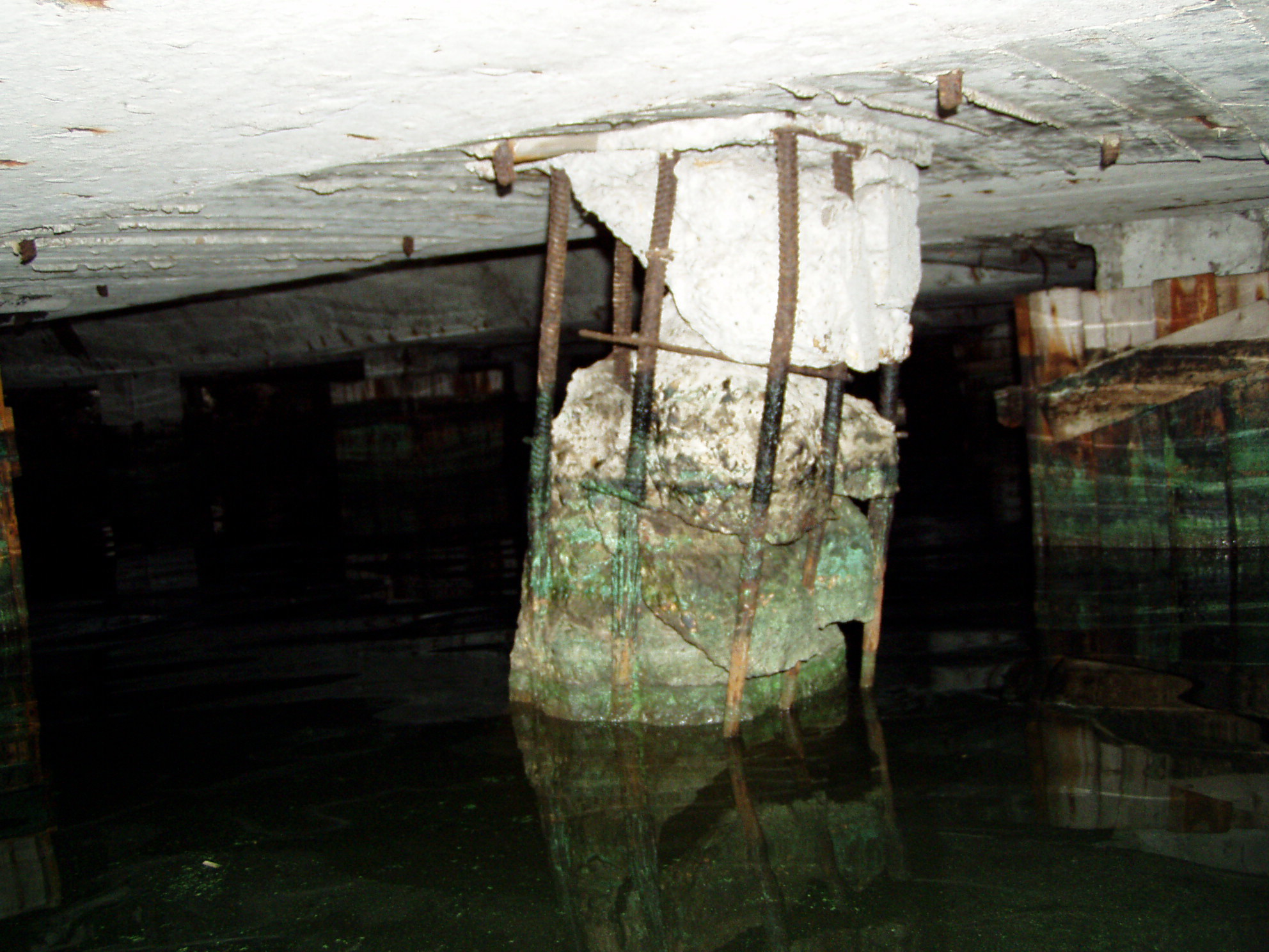
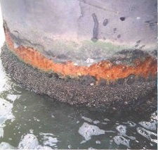
Many waterborne structures on pile foundations are designed for a service life of 40-50 years. So, some of them are practically close to the end of their normative service life. Furthermore, problematic situations arise with piles operating in harsh natural or industrial conditions, leading to intense physical wear. Not only physical (mechanical) damage poses a danger, but also erosion of the seabed around the piles (for example, by bottom currents or jets of water from ship pro-pellers). Soil sliding along the ground slope around the pile also worsens the op-erating conditions of pile structures.As experience shows, the basic characteristic damage to reinforced concrete piles of waterborne facilities is the infringement of the concrete cover, and deeper (sometimes extending to all sections of the pile) cracking and washing up of the concrete. It is necessary to note also corrosion of steel reinforcement both in a tidal/splash zone, and in places of pile heads connection with the top structure (samples of typical pile damage are presented in Fig. 3).
  |
 |
| Fig. 3. Reinforced concrete piles of the waterborne structure after significant physical wear |
The main reasons for corrosion in steel pipe piles can be broken down into envi-ronmental factors, specific high-activity zones, and mechanical/biological influ-ences. Some related samples of damaged steel piles are shown in Fig. 4.
 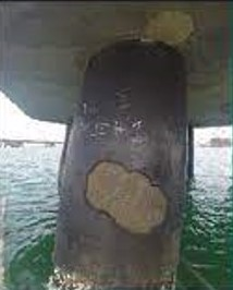 |
| Fig. 4. Steel pipe piles of the waterborne structure after corrosion attacks |
Duly repair and fast restoration of design parameters of all damaged piles of em-bankment and berthing structure is, obviously, an actual task but not always fea-sible in a concrete operational situation (technological problems, influence of seasonal climatic conditions, duration of performance of works, etc.).
3. Proposed design approach regarding the actual technical condition of the structure
Thus, physical wear of constructive elements of the structure may be one of the basic design parameters which are taken into account at definition of re-serve/deficiency of bearing capacity of an operated facility.
Below are presented substantive provisions of a suggested method that can be applied in the practice of technical operation of urban waterborne constructions to determine a more grounded operation and maintenance regime.
The technique is based on an approach that considers the redistribution of load-ings on the structure’s basic bearing elements and, accordingly, the redistribu-tion of forces as the initial (passport) characteristics of piles have changed due to physical wear.
Let’s enter the following designations:
- n- number of cross pile rows within the limits of one section of the struc-ture,
- k- number of piles in one cross pile row,
- N- total transversal (normal to quay front line) load on the section,
- J- passport rigidity (the moment of inertia, the area of cross-section) of the pile, regardless of its physical wear,
- Ji- real rigidity (the moment of inertia, the area of cross-section) of the “i” pile row regarding its physical wear,
- KNi - factor of rigidity redistribution of the “i” cross pile row in view of its physical wear,
- RNi - factor of loading redistribution on the “i” cross pile row in view of its physical wear.
Niо=N/n; (i=1,2,…, n ), (1)
and loading on the “i” cross pile row of the considered section regarding physical wear:
Ni=N x KNi ; (i=1,2,…, n ), (2)
thus KNi = Ji/[∑Ji]; (i=1,2,…, n ), (3)
where
Ji = (S1i+ S2i+…+ Ski) J; (4)
Sкi –a degree of physical wear of the cross-section of the “k” pile at the “i” row of the considered section (i.e., percent of the area of the cross-section remaining in work); 0≤ Sкi ≥1.
Thus, the factor of loading redistribution on the “i” cross pile row in view of its physical wear can be determined as
RNi = Ni/ Niо. (5)
When calculating refined forces distribution in basic elements of the structure (in piles and in the top structure) regarding physical wear of pile supports, loading on each transverse pile row should be corrected (redistributed) according to the formula (2). For this procedure, pile rigidity must be set in view of the degree of physical wear determined by the results of visual and tool inspections.
4. Design case and proposed method application
Let's consider the application of the developed technique using the example of calculating a piled berth. Such a structure is widely distributed in ports of the Black and Azov seas.Structure’s foundation consists of five rows of reinforced concrete piles (dimensions 40×40 cm and 45×45 cm), spaced in a longitudinal direction with a step 2,5 m in front and rear rows and with a step 5,0 m in three interim rows. In the rear row, vertical and inclined piles alternate. The top structure consists of modular reinforced concrete plates and beams. Constructive and calculation schemes of the berth are presented in the Fig. 5 and 6.
On the available data, owing to long-term operation, the pile supports of the considered berth have undergone certain physical wear. The wear degree for one of the most damaged sections is reflected in Table 1. We shall note that according to the results of visual and tool inspection, piles "С4" and "D8" have undergone significant damage down to full destruction of concrete and an exposure of the basic bearing reinforcement and, as a consequence, its corrosion damage (it is similar to the state of the piles represented in Fig. 3).
Design factors of rigidity redistribution of the pile rows and loadings on them for the considered structure’s section, obtained as a result of application of dependences (1) - (5), are presented in Table 2.
 |
| Fig. 5. A cross-section of the piled structure. The calculation scheme. |
  |
| Fig. 6. Pile location (top view). |
Table 2 The basic results of the calculations of the piled structure
| Cross pile rows | Maximal bending moment (normative / designed) |
||||||
| per one pile, kNm | in top structure, kNm/m |
||||||
| longitudinal pile rows | |||||||
| A | B | C | D | E | inclined row | ||
| Account of minimum wear |
22,02 | 19,20 | 25,04 | 35,35 | 49,18 | 59,72 | 87,09 |
| 30,07 | 26,22 | 34,20 | 48,27 | 67,16 | 81,56 | 118,93 | |
| Account of maximum wear |
16,97 | 16,08 | 11,44 | 25,74 | 38,50 | 47,20 | 67,10 |
| 23,17 | 21,96 | 15,62 | 35,15 | 52,58 | 64,46 | 91,63 | |
| Account for initial design parameters regardless of wear |
17,32 | 17,74 | 23,69 | 32,09 | 44,93 | 55,15 | 81,49 |
| 23,65 | 24,22 | 32,35 | 43,82 | 61,36 | 75,31 | 111,28 | |
5. Conclusions
- In comparison with initial design efforts in the basic bearing elements of a construction, the account of a real degree of physical deterioration of pile support has led to appreciable redistribution of efforts
- In pile rows with the minimal physical wear, the bending moments in sections with the greatest values of efforts have increased by 6-27 % (the greatest increase of effort falls on the front pile row); efforts in elements of the top structure have increased by 7 %
- In pile rows with the maximal physical wear, the bending moments in sections with the greatest values of efforts were reduced to 2-52 % (the most significant efforts reduction falls to middle rows with the most damaged piles which practically do not participate in bearing external loadings); efforts in elements of the top structure were reduced to 17 %
- Due to redistribution of efforts between pile supports, the difference in the bending moments in sections with the greatest values of efforts for cross pile rows with the minimal and maximal physical wear makes 1,2-2,2 times (the greatest difference is fixed, naturally, for the most damaged pile rows); efforts in elements of the top structure differ thus in 1,3 times.
M. Doubrovsky, M. Poizner (2016). Innovative development of coastal, port, and marine engineering. Lambert Academic Publishing, Germany, 125 p.
Doubrovsky M., Kusik L., Dubravina V. (2021). Bearing Capacity of Tubular Piles: Technological Improvements and Model Testing. Advances in Geoengineering along the Belt and Road. BRWSG 2021. Lecture Notes in Civil Engineering, vol 230. Springer, Singapore, 137-154. https://doi.org/10.1007/978-981-16-9963-4_11.
M. Doubrovsky, V. Dubravina, V. Shokarev et al. (2022). Ensuring the piles bearing capacity under pressing loads. Proceedings of the 20th International Conference on Soil Mechanics and Geotechnical Engineering – Rahman and Jaksa (Eds). © 2022 Australian Geomechanics Society, Sydney, Australia, 3247-3252. ISBN 978-0-9946261-4-1.
L. Zhang, H. Wang, Q. Li. (2023) Degradation mechanisms and bearing capacity assessment of corroded steel piles in marine environments. Marine Structures. 522-537. Doi:10.1016/jmarstruc.2023.103456
M. Hassan, S. Rahman, A. Ahmed. (2023) Effects of corrosion and cyclic loading on the lateral capacity of steel tubular piles. Soil Dynamics and Earthquake Engineering. Doi:10.1016/j.soildyn.2023.107789
.jpg) |
Michael Doubrovsky is a Professor at Odessa National Maritime University (Dept. of Marine and Civil Engineering). At this university, he founded a scien-tific school dedicated to kinematic methods for studying the structure-soil-water system. He is also engaged in innovative developments in the field of sheet pile walls and pile supports for engineering structures. M. Doubrovsky participated in the inaugural meeting of the IPA in 2007 and has been actively involved in its activities since then. |
| << Previous | Newsletter Top | Next >> |