
Newsletter Volume 11, Issue 3 September 2026
Corrosion Protection and Strengthening of Port and Harbour Steel Structures Using the Reinforced Concrete (RC) Encasement Method
1. Preface
Port and harbour steel structures used in marine environments are exposed to severe corrosive conditions over long periods. This makes the selection of appropriate corrosion protection methods extremely important. Although many corrosion protection techniques exist depending on the intended application, recent demands for the extension of infrastructure service life, improving maintenance and repair (restoring structural performance), and even enhancing structural performance beyond the original design have grown. In light of these needs, this paper focuses on the RC encasement method. This method is one of the corrosion protection techniques with a relatively long expected service life which has many applications to steel sheet piles and steel tubular pile walls, and can also serve effectively as a strengthening method depending on the situation.
2. Corrosion Rates of Steel Structures
Corrosion of steel structures in port and marine environments has been described in several standards that outline the relationship between corrosive environments and corrosion rates. This section introduces Japanese, European, and international standards. Since these standards are based on typical marine conditions in temperate climates, regions with different corrosive environments require evaluations that reflect local conditions. For example, in the Red Sea—where the salinity is around 4%, compared with the global average of about 3.5%—the combination of relatively high seawater temperature and air temperature is known to result in corrosion rates of unprotected steel, reaching as high as 1.0 mm per year.
| 1) |
Japan: Guidelines for Maintenance and Repair of Port and Harbour Facilities (Coastal Development Institute of Technology)
In this manual, the average corrosion rates obtained from unprotected steel structures in marine environments are compiled, and the corrosion rates for each corrosive environment are published as standard values (see Fig. 1 and Table 1). 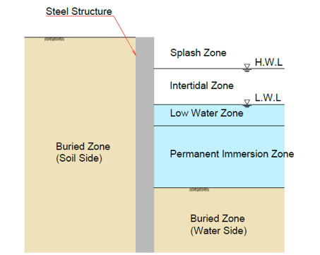
Fig. 1. Corrosive Environment of Marine Structure
Table 1. Standard Corrosion Rates of Steel Structures
|
| 2) |
Japan: Technical Standards and Commentaries for Port and Harbour Facilities in Japan (The Japan Port and Harbor Association)
In this standard, the average values of corrosion compiled from surveys of existing steel structures are presented in Table 2. It should be noted that the corrosion rate of localized corrosion can greatly exceed the values shown in Table 2. Although the corrosion rate in the buried zone is generally low, it can become more significant depending on the physical properties of the soil. These physical properties include particle size, water content, and soil resistivity, along with soil chemical properties which include pH, dissolved oxygen and microbial activity.
Table 2. Standard Corrosion Rates of Steel Structures
|
|||||||||||||||||||||||||||||||||||||||||||||||||||||||
| 3) |
Europe: BS EN1993-5:2007 Eurocode 3-Design of steel structures-Part5: Piling
In the Eurocode the predicted corrosion loss of steel materials up to a maximum of 125 years has been published based on the measured corrosion loss over 5 to 25 years, as shown in Table 3.
Table 3. Corrosion Rates of Steel Structures in Eurocode
|
|||||||||||||||||||||||||||||||||||||||||||||||||||||||
| 4) |
International: ISO 9223:2012 (Corrosive Environment Classification) and ISO 9224:2012 (Guideline values for corrosion of metals and alloys)
In ISO 9223, the corrosion rate for the first year of exposure is determined from exposure tests and measurements of environmental factors. The corresponding corrosion category is then selected from the corrosion classification table. Subsequently, in ISO 9224:2012, the corrosion loss is calculated based on the first‑year corrosion rate and the corrosion category, taking into account factors such as the type of steel, annual average temperature, annual average relative humidity, sulfur dioxide deposit, chloride deposit, exposure duration, and the reduction in corrosion rate over time due to deceleration. The formulas and detailed indicators are not included here (refer to the relevant standards for further information). Because this standard subdivides parameters, it offers high operability in calculations. However, when the first‑year corrosion rate or corrosion environment is not sufficiently understood, uncertainty increases. This results in the drawback that substantial preliminary investigation is required for evaluation. |
|||||||||||||||||||||||||||||||||||||||||||||||||||||||
As described above, it is possible to maintain the soundness of steel structures after they are put into service by estimating the corrosion loss from the corrosion environment and the design service life, and by adding an appropriate corrosion allowance before installation. However, adding a corrosion allowance can sometimes compromise economic efficiency. Also, in highly corrosive environments—from L.W.L. −1.0 m to the splash zone—there is a risk of corrosion progressing more rapidly than expected due to accelerated low‑water corrosion. For this reason, it is considered desirable to apply corrosion protection methods rather than to rely solely on corrosion allowance. In fact, for steel structures in Japanese ports, it is a general principle that countermeasures based solely on corrosion allowance are not used, except for temporary structures.
3. Corrosion Protection Methods Used for Port and Harbour Steel Structures
Corrosion protection methods used for port and harbour steel structures are broadly classified into cathodic protection and coating protection. It is common practice to apply cathodic protection to portions below the M.L.W.L. and coating protection to portions located 1.0 m or more above the L.W.L. (see Fig. 2).
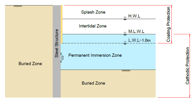
Fig. 2. Application areas of corrosion protection methods
Table 4 below shows the classification of corrosion protection methods.
|
Coating Protection
|
Protection Painting System
|
|
|
Organic Coating System
|
Protective Coating System
|
|
|
Ultra-High-Build Coating System
|
||
|
Underwater-Curable Putty-Type Coating
|
||
|
Petrolatum Tape Wrapping System
|
||
|
Metallic Coating Method
|
Protective Metallic Coating
|
|
|
Metallic Thermal Spray Coating
|
||
|
Inorganic Protective Coating System
|
Cement Mortar Coating
|
|
|
RC Encasement Method
|
||
|
Electrodeposition Coating
|
||
|
Cathodic Protection
|
Galvanic Anode Cathodic Protection(GACP)
|
|
|
Impressed Current Cathodic Protection(ICCP)
|
||
4. Overview of RC Encasement Method
The RC encasement method is a technique in which concrete, reinforced with steel bars, is applied as a protective covering over steel structures, such as steel sheet pile walls or continuous steel tubular pile walls. Its fundamental corrosion protection mechanism is based on the environmental shielding effect provided by the concrete cover, combined with the alkalinity of the cement, which passivates the steel surface and protects it from corrosion. Because the concrete encasement offers high resistance to external forces, it serves a dual purpose as a structural reinforcement method. This method is applied in environments that are highly exposed to wave action, or in situations where vessels may come into direct contact with the protective covering, or where resistance to external impacts such as drifting debris is required. As shown in Fig.s 3 and 4, there are two approaches: one in which the formwork is removed after the concrete has hardened, and another in which precast concrete panels or similar materials are used as permanent formwork.
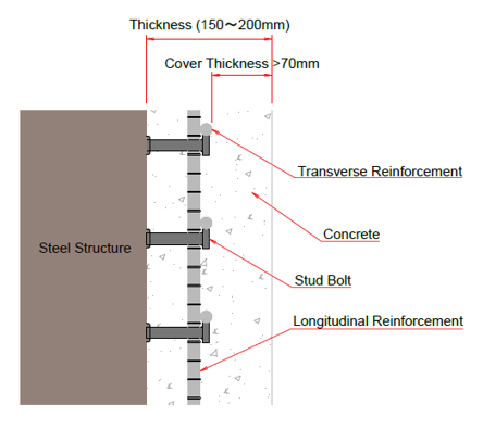
Fig. 3. Cross Section of RC Encasement
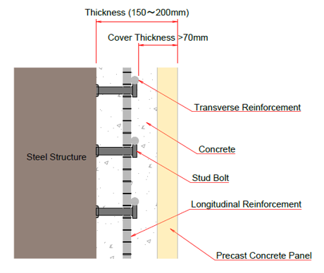
Fig. 4. Cross Section of RC Encasement with Precast Concrete Panels
The RC encasement method can be applied not only as a corrosion protection technique for newly constructed structures - because it can be executed on-site - but also as a means of “repair” and “strengthening”. The repair is aimed at restoring the structural performance of unprotected or corrosion‑degraded steel structures. The strengthening is aimed at improving their structural performance.
5. Design and Construction Flowchart for the RC Encasement Method
The design procedure for harbour and port steel structures using the RC encasement method is shown in Fig. 5.
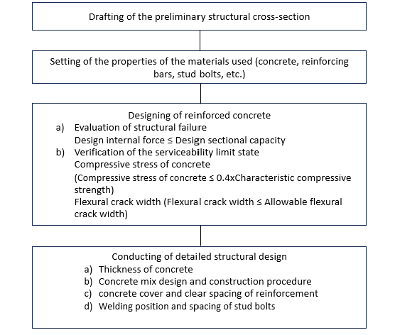
Fig. 5. Design Flowchart for the RC Encasement Method
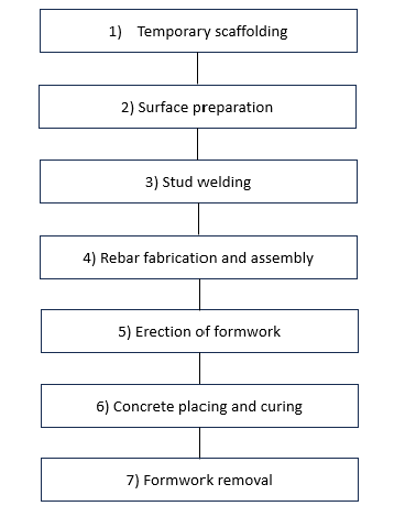
The construction procedure of the RC encasement method is shown in Fig.s 6 and 7.
| 1) |
Temporary Scaffolding
Temporary scaffolding must have sufficient strength to withstand external forces such as waves and currents and must be structured so that all work can be carried out safely and seamlessly. In general, system scaffolding and pipe and coupler scaffolding are often used. |
| 2) |
Surface Preparation
Prior to stud welding, it is necessary to remove any contaminants such as rust, as well as any marine growth which may adhere to the steel sheet piles or steel tubular piles. Methods for surface preparation include blast cleaning, the use of power tools (such as air sanders or mechanical chipping hammers), the use of hand tools (such as scrapers or wire brushes) and high‑pressure water cleaning. |
| 3) |
Stud Welding
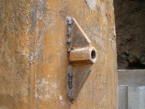
Stud bolts are welded onto the surface of the steel sheet piles or steel tubular piles to integrate them with reinforced concrete. There are two types of stud welding: open-air stud welding and underwater stud welding. For construction carried out underwater or in environments affected by water, underwater stud welding is used. The standard stud diameters are 16 mm and 19 mm. In the case of underwater stud welding, the welding position becomes horizontal, so the maximum standard applicable stud diameter is limited to 16 mm. If underwater welding of stud bolts with diameters exceeding 16 mm is required, it is necessary to establish project‑specific construction management criteria according to site conditions. Even in such cases, the upper limit diameter for underwater stud welding remains 19 mm. Unlike open-air welding, bending tests are not required for quality inspection for underwater stud welding. Instead, it is mandatory to submit all bizigraphs (graphs showing the relationship between welding current and welding time). |
| 4) |
Rebar fabrication and assembly
Reinforcing bars used for RC encasement shall be bent reinforcing bars specified in JIS G 3112 “Steel Bars for Reinforced Concrete.” Generally, the assembly of reinforcing bars is carried out underwater; however, when cranes or other lifting equipment can be utilized, the reinforcement can be preassembled on land and then lowered into place. Methods for tying reinforcement include using binding wire ties, tying clips, or spot welding; however, when considering external forces such as waves and water currents, it is necessary to select a method capable of maintaining the assembled reinforcement in position until the concrete is placed. |
| 5) |
Erection of formwork
There are two types of formwork: temporary formwork, which is removed after the concrete has hardened, and permanent formwork, which uses precast concrete panels or similar materials and remain as part of the structure. In either case, the formwork must have sufficient strength to withstand the weight of the concrete and other external forces during underwater concrete placement. It is also important to ensure that there is no leakage of mortar or seawater through gaps in the formwork joints. Furthermore, because there should be no filling gaps in the concrete placement, a concrete thickness of 150 mm or more is generally adopted to ensure the construction of reliable structures. |
| 6) |
Concrete placing and curing
RC encasements are constructed underwater or in water‑containing environments. Therefore, the concrete materials used include underwater‑separating concrete (general underwater concrete) and anti‑washout concrete (high‑viscosity concrete containing special admixtures). In marine and harbour environments, anti‑washout concrete is considered preferable because it is less prone to material segregation and offers excellent filling performance due to its high fluidity. However, when anti‑washout concrete is placed in areas not in contact with water, it exhibits significant drying shrinkage and has low resistance to frost damage. For this reason, in environments where these effects are a concern, general underwater concrete is recommended. From the standpoint of constructability, general underwater concrete is used when there is sufficient clearance between the wall and the formwork and when uniform placement by a concrete pump truck is possible. Otherwise, anti‑washout concrete tends to be used. |
| 7) |
Formwork removal
Formwork is removed after confirming that the concrete has reached the required strength. After removing the formwork, the separator holes and similar openings must be filled with a water‑curing epoxy resin or equivalent material. |
6. Composite Section Properties of Steel and Reinforced Concrete
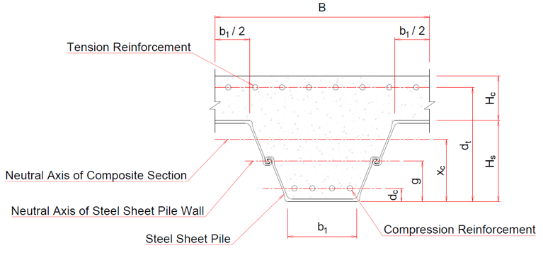
When steel structures such as steel sheet piles or steel tubular piles are covered with reinforced concrete to form a composite wall, the design sectional forces of the composite wall shall be calculated in the same manner as those of a reinforced concrete section (see Equation 6-1 and Fig. 7). In this calculation, the steel sheet piles or steel tubular piles may be regarded as reinforcement having an equivalent cross‑sectional area.
S=Es{(xc-dt)2At + (xc-dc)2Ac + Isg + As(xc-g)2} + Ec{1/12・(b2-b1)/Hs・xc4 + b1/3・xc3} ……(6-1)Es : Young’s modulus of steel sheet piles (N/mm2)
Ec : Young’s modulus of concrete (N/mm2)
xc : Height of the neutral axis of the composite section (mm)
Hs : Height of the steel sheet pile wall (mm)
b1 : Flange width on the compression side of the steel sheet pile wall (mm)
b2 : Flange width on the tension side of the steel sheet pile wall (mm)
Ac : Cross‑sectional area of compression reinforcement (mm2)
At : Cross‑sectional area of tension reinforcement (mm2)
As : Cross‑sectional area per one set of steel sheet piles (mm2)
dt : Distance from the compression edge to the center of the tension reinforcement (mm)
dc : Distance from the compression edge to the center of the compression reinforcement (mm)
g : Distance from the compression edge to the neutral axis of the steel sheet pile wall (mm)
Isg : Moment of inertia per one set of steel sheet piles (mm4)
It is generally accepted that stud bolts are treated as “shear connectors for stress transfer” and are not included in the calculation of the sectional properties of the wall.
7. Maintenance and Repair of Reinforced Concrete
The repair method for the damage of reinforced concrete varies, depending on the scale of the damage. For small cracks, minor defects, or limited areas of exposed reinforcing steel, repair methods using underwater‑curing epoxy resin materials are applied. However, for large cracks, significant defects, or extensive exposure of reinforcing steel, the damaged concrete is removed and reconstructed.
- Inspection of crack conditions
- Cutting concrete along the crack
- Filling crack with underwater‑curing epoxy resin
- Quality Inspection
- Inspection of conditions
- Removal of the deteriorated surface portion
- Coating with underwater‑curing epoxy resin
- Quality Inspection
- Inspection of conditions
- Removal of damaged concrete
- Replacement of damaged reinforcing bars and stud bolts
- Installation of formwork
- Concrete placement and curing
- Formwork removal
- Quality Inspection
8. Non‑composite RC Encasement Method Using Precast Concrete Panels (Permanent Formwork)
Up to this point, corrosion‑protection methods that combine reinforced concrete and steel members as structural components have been described. However, when the structure is supported solely by steel members, the concrete can be treated as a non‑structural element. This allows the configuration of stud bolts and reinforcing bars to be simplified. In this case, precast concrete panels are used as permanent formwork, and concrete is placed to secure the precast panels to the steel members and to provide corrosion protection (see Fig. 8).
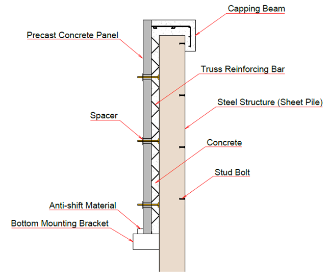
Fig. 8. RC Encasement Method using Precast Concrete Panels
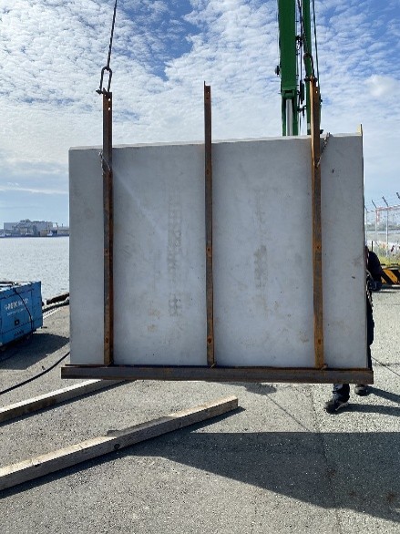
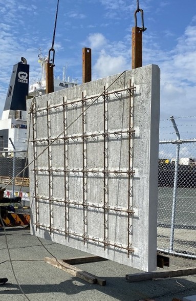
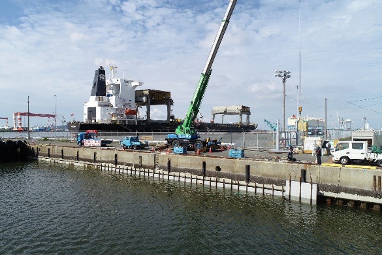
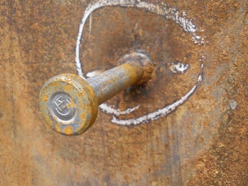
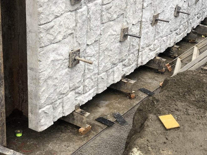
In recent years, there has been a growing trend toward applying corrosion protection methods that use a non-composite concrete covering system utilizing precast concrete panels. This emphasizes more straightforward constructability. The installation of the concrete panels is based on segmented construction, and there are construction records of wall heights up to 17.6 m (as of April 2026). Fig.s 9 through 14 show an overview of the precast concrete panels. (Photographs courtesy of Kyowa Concrete Industry Co., Ltd.)
9. Conclusion
The RC encasement method has been widely used for corrosion protection of many port and harbour steel structures because, among coating-based corrosion protection methods, it offers relatively high cost-effectiveness and can provide a long design service life. In addition, its ease of maintenance makes it well suited for planning and implementing lifecycle management, which is another reason for its extensive application.
Furthermore, the RC encasement method can restore the structures to a level of design sectional strength sufficient to stably maintain their cross-section. This is so, even if the mechanical performance originally possessed by the steel structure has been reduced due to corrosion. It is also effective when structural reinforcement is required, such as improving seismic performance or revising applied loads due to the increasing size of target vessels. The thickness of the concrete placed on the steel surface and the combination with stud bolts or reinforcing bars that transfer stresses can be freely selected. As such, the method offers a high degree of design flexibility and can accommodate a wide range of required structural performance.
Moreover, unlike pre-applied coating methods, this method is implemented after the steel structure has been installed, making it easier to ensure the soundness of corrosion protection performance. Given that it also allows for easy landscape design, further application of this method is anticipated in the future.
References
Coastal Development Institute of Technology, Guidelines for Maintenance and Repair of Port and Harbour Facilities, 2022 Edition (in Japanese)Corrosion Protection and Repair Method Research Association, Practical Handbook for New Corrosion Protection, Repair Methods, and Maintenance of Port Structures, 2013 Edition (in Japanese)
Japan Society of Civil Engineers, Standard Specifications for Concrete Structures - Design, 2022 Edition (in Japanese)
Japan Society of Civil Engineers, Standard Specifications for Concrete Structures - Construction, 2022 Edition (in Japanese)
Japan Society of Civil Engineers, Specification for Design and Construction of Anti-washout Underwater Concrete (Draft), 2021 Edition (in Japanese)
BS EN 1993-5:2007, Eurocode 3 Design of steel structures - Part5: Piling
UK National Annex to Eurocode 3: Design of steel structures - Part 5: Piling
ISO 9223:2012 Corrosion of metals and alloys — Corrosivity of atmospheres — Classification, determination and estimation
ISO 9224:2012 Corrosion of metals and alloys — Corrosivity of atmospheres — Guiding values for the corrosivity categories
| << Previous | Newsletter Top | Next >> |